
Page 46 - Yamaha Marine Zubehoer 2026
P. 46
Rigging Diagrams
How to read the diagram
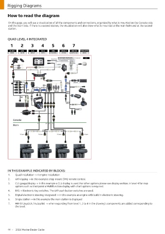
On this page, you will see a visualization of all the components and connections, organized by what is mounted on the Console side
and the Stern side. If there is a second station, the visualization will also show what is mounted at the main helm and at the second
station.
QUAD LEVEL 4 INTEGRATED
1 2 3 4 5 6 7
SINGLE 6X9 CL5 EKS DES SINGLE HM-EX THRUSTER
DES
TWIN
QUAD
TRIPLE
DES
DES
DES
INTEGRATED
ENGINE
ENGINE
STEERING
INTEGRATED
INTEGRATED
ENGINE DEC TM DISPLAY SWITCH INTEGRATED STATION JOYSTICK / AP DRIVER
ENGINE
1.2.i
2.1
2.2.i
4.1
3.1
4.2.i
4.4.i
1.1
Bow thruster driver and harness must be Do not use! 3.2.i
Do not use!
To Fuel Tank sourced through bow thruster manufacturer
To network thruster
Main
To GPS Optional
CS
C CP To Heading
xtr
E
P Extraa e 6Y9
Devic
Device
CS CP CP To 2nd ST Network
Only
S To BCU/
2nd ST
To SW Panel Harness P CP CS SS Harness
Quad
To RC
Harness
To boat mounted
Prop Lights
Console
P CP CS S
Stern
P CP CS S
To Engine To Engine To Engine To Engine
IN THIS EXAMPLE INDICATED BY BLOCKS:
1. Quad installation -> 4 engine installation
2. 6X9 rigging -> in this example a top mount (TM) remote control.
3. CL5 gauge/display -> in this example a CL5 display is used. For other options please see display section. In level 4 for map
options such as trackpoint a Multifunction display with chart options is required.
4. EKS -> Electronic Key switches. The 6X9 push button switches are used.
5. Digital electronic steering Integrated -> in this example an engine with build in electronic steering.
6. Single station -> in this example the main station is displayed
7. HM-EX Joystick / Autopilot -> when expanding from level 1, 2 to 4 in the drawing’s components are added corresponding to
the level.
44 – 2026 Marine Dealer Guide